Motor Mounts
As explained during the redesign of the front assembly, the front motor mounts have already been changed to make more free space at the front of the robot. However, this design is lower than wanted and the motor PCB of the front right wheel is in the way of the new lipo. Therefore, each motor mount needs to be higher, and the holes to fix the motor in the front right motor mount need to be changed. Also, we have decided to have a company manufacture the motor mounts so that they can be of better quality than what we can make. Due to this decision, we can have threaded holes in the motor mounts, which means we have to use less nuts and therefore it saves us money. However, for the holes at the bottom of the motor mounts, we still need to put nuts like in the previous design. This is necessary because, with a thread, the screws will get loose during the games due to vibrations and the fact that they are facing downwards. However, the nuts have a rubber part at the end which prevent the screws from getting loose. Therefore, we have to make holes to slide in nuts at the bottom of each motor mount.
Final Designs
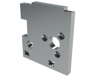
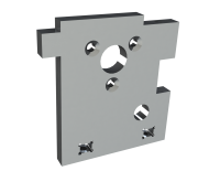
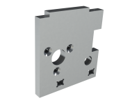
With this new design, the middle plate is now resting on the motor mounts at a height of 58mm (54mm previously). The middle plate is now screwed on the motor mounts, one on each back and two on each front motor mount (the middle plate was directly connected to the bottom plate with two metal support before). This will make the middle plate fixed in a better way in the robot. Also, as explained above, each of the screw holes to connect to the middle plate have a M3 thread in them. The following pictures show (from left to right) the front left, back and front right motor mounts.
The two motor mounts at the back are the exact same, with a chamfer for the motor screw holes on each side. The motors at the back are still at a 90 degree angle with the top of the motor mounts, like in the previous design. However, as explained here, the front motors' angle had to be changed. Therefore, the front right motor is now at a 85 degree angle and the front left motor is at a 70 degree angle with the top of their motor mount.
Drawings
In order to have a company manufacture these motor mounts, it is necessary to make drawings of the parts. With these drawings, the company will know how to manfacture the motor mounts exaclty how we want them. Therefore, it is important to properly make these drawings!
In the old design, the problem with the manufacturing was that the faces of the motor mounts were not completely flat. It was especially a problem with the face resting on the bottom plate, because then the motor mounts and so the wheels would not be at a 90 degree angle with the floor which increased the issue where only three wheels touch the floor instead of four. Therefore, the drawings must indicate that the faces need to be flat. Also, since we want to have threads in the motor mounts, the drawing needed to show this. We also added a thread runout in each tapped hole to make sure the motor mounts can last longer and have a better connection with the middle plate. Finally, all the dimensions were added, with the most important ones written as TED (Theoretically Exact Dimensions). You can find the technical drawing of the front left motor mount here. For more information about how to make a technical drawing in the right way, click here.


