Available Design Space
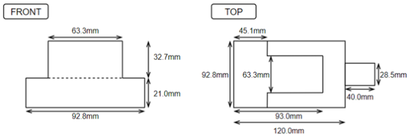 At the beginning of September 2021, the front assembly is mounted on the metal bottom plate of the robot. At this location, the design space is limited by the front motors on the assembly's sides and by the middle plate above it. So, the available space is as shown in the following figure.
The small space of 40.0 mm by 28.5mm is occupied by the stroke for the solenoids that move the kicker and chipper. The main constraint in the design space is caused by the position of the front motors. Therefore, changing the configuration of these motors will create extra space to design the front assembly.
Creating Extra Design Space
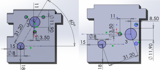
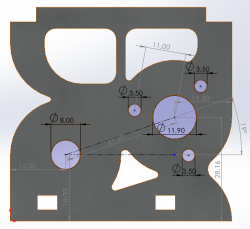
As explained above, the front motors' position needs to be changed in order to free space for the front assembly. To do so, we can shift the motors a bit to the back on the motor mounts, so that the motors are located a bit further in the back. This implies that the holes through which the motor is mounted must shift as shown in the two figures below. The figure on the left shows the design of 20-21 and the first hole placement changes. The figure on the right shows the final hole placements of the new motor mount. Indeed, with the first redesign shown in the left figure, the motor's PCB went from a 90 degree to a 45 degree angle with respect to the top of the motor mount. However, with a 45 degree angle, the PCB collided with the lipo. Therefore the motor's screw holes were modified to increase that angle and make sure everything fit properly in the robot. Also, with this new design, there is a bit more space for the front assembly, without making major changes to the bottom plate. Though, a consequence of this design decision is that the middle plate has to be adjusted accordingly, which is not a major constraint at all.
This modification will create space in both the depth and width directions. The motor mounts are mounted at a 30 degree angle with respect to the front of the robot. The hole for the motor's shaft was shift 13.9 mm to the right on the motor mount, which freed up 13.9mm * cos(30) = 12 mm in the depth direction and twice 13.9mm * sin(30) = 7 mm in the width direction (which gives 14 mm extra space in total). Note that, due to the change of the orientation of the holes around the hole through which the shaft of the motor is mounted, the motor is mounted under an angle, which requires a redesign of the middle plate.
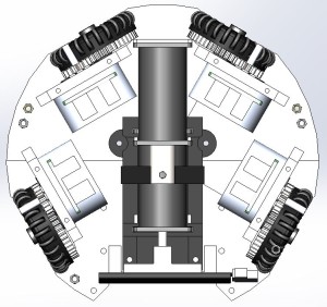
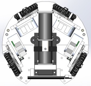
The figures below show a top view of the old and new configurations of the motors. Due to this change, there will be more space at the front of the bottom assembly. The PCB of the motors will point slightly forwards, which takes up some of the space. However, this is only a minor drawback of the new configuration. The extra space obtained at the bottom weighs up for this.
