Wheel Assembly
 This 23-24 wheel assembly has several changes:
- Wheel Main Frame
- Shaft Connector
- Motor
- Motor Mount
The wheel assemblies are connected with two screws to the bottom plate. Assembly consists of an OmniWheel, motor mount, maxon motor with its PCB and a shaft connector.
The math for calculating the wheel design can be found here: Math Wheels
OmniWheel
The wheels were made by the first RoboTeam and have almost not changed since then. This year the main frame is changed. The design philosophy is used during the redesign. Mainly the hole that connects the wheel to the shaft is changed. This is done because of the change to direct drive. Furthermore, the wheels are now made by SLS printing using nylon PA12, which is done at mareco prototyping. This differs from the last wheel design, which was made by CNC milling POM. Also, the space for the subwheel shaft is increased, compared to last wheel design, to make sure the subwheels can move smoothly without facing a lot of friction
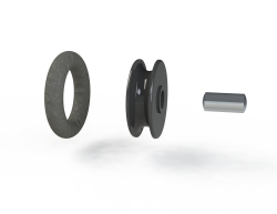
The wheels are made of several parts as you can see in the figures on the right. The most important one is the omniwheels which allow the robot to move in any direction without having to rotate its wheels (an exploded view of an omniwheel can be seen on the right of the exploded view of the wheel). There are twenty-five OmniWheels per wheel, they each have a rubber O-ring that is put around a black plastic part which rotates freely around a small metal shaft. This shaft is stuck between the two black plastic parts of the wheel such that to omniwheels cannot fall off. The two plastic parts (frame and cap) are screwed together as one whole assembly. A nut is used to fix the wheel to the shaft connector. To transfer the motor torque to the wheel a form fit between the shaft connector and the wheel is used.
Drawings of the wheels can be found here:
Motor Mount
 Due to the change to direct drive the motor mounts are changed this year. The motor mounts consist of tapped m3 holes which makes it possible to connect the mount to the bottom plate. The middle plate rests on top of the motor mounts. The motor mounts have threaded holes on the top side to fix the middle plate to the motor mounts. The wheel's motor is connected to the motor mount with three screws (m3 torx) in the figure. Furthermore, a slot is added to the motor mount to make sure the connectors of the motor do not scratch against the motor mounts. All-wheel assemblies consist of the same motor mount and are made of stainless steel. The mounts are made at MCM Marknesse by the use of laser cutting and drilling the holes at the bottom and top afterwards.
The drawing of the motor mount can be found here:
Motor
 The 23-24 team got the ECXFL32L KL A HTQ 48V motor from maxon. They come with their own PCB into which the motor cable and motor encoder cable can be plugged. Compared to the last robot, the last robot has bulky PCB's, which took quite a lot of space. Therefore with the use of these motors space is created to fit in the new solenoids and the front assembly. The motors are connected to the motor mount with the use of three screws(m3 torx). The datasheet of these motors can be found here: datasheet. To transfer the motor torque to the wheels a custom-made shaft connector is glued to the motor shaft.
Shaft connector
 The motor torque is transferred by the use of a shaft connector to the wheel. The shaft connector is glued to the motor shaft using Loctite 638. A nut is used to press the wheel against the shaft connector. With the use of a square form fit the torque is transferred to the wheel. The shaft connectors are produced at TCO.
The drawing can be found here

