Wheel Assembly
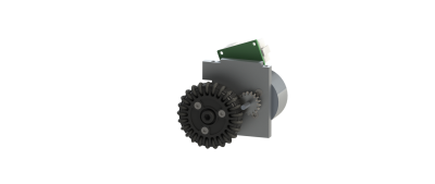
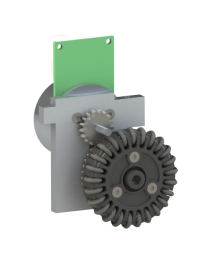 The wheel assembly did not change that much with respect to the 20-21 robot. The motor mounts have been redesigned as a consequence of the new front assembly. Also all wheels, sub-wheels and gears have been cleaned.
The wheel assemblies are connected to the bottom plate with two screws each. There are two left wheel and two right wheel assemblies per robot. They are each made of a wheel, a motor mount, a Maxon motor with its PCB and the transmission between the motor and the wheel.
OmniWheels
The wheels were made in the first RoboTeam year and have almost not changed since then (only the material of the gear was changed in 2019-20). They were made by a company in Hengelo called Hemabo, and has not needed major changes since year one.
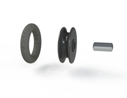
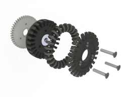 The wheels are made of several parts as you can see in the figures on the right. The most important one being the omniwheels which allow the robot to move in any direction without having to rotate its wheels (an exploded view of an omniwheel can be seen on the right of the exploded view of the wheel). There are twenty-five omniwheels per wheel, they each have a rubber O-ring that is put around a black plastic part which rotates freely around a small metal shaft. This shaft is stuck between the two black plastic parts of the wheel such that to omniwheels cannot fall off. Those plastic parts along with the plastic gear are attached together using three screws. Finally, in one of the black plastic parts, there is a ball bearing through which the wheel's shaft goes. This shaft is screwed to the motor mount in order to fix the wheel in place.
Due to vibrations, the three screws in the wheel can get lose and can even fall out. If this happens, the robot is also likely to lose omniwheels. This problem can be fixed by using loctite to keep the screws in place.
When the robot drives on the field, quite some stuff can get stuck on the gears and in the wheels. Because of this, the wheels and the omniwheels might rotate less smooth. Therefore, the wheels of the robots need to be cleaned every once in a while to ensure proper performance of the robots. All wheels have been cleaned before RoboCup 2022.
Motor Mount
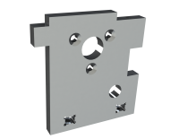 The motor mounts are each connected to the bottom plate with two screws, there are two rectangular holes at the bottom in which M3 nuts are slided in so that the connection with the bottom plate is sturdy. The middle plate rests on top of the motor mounts. The motor mounts have threaded holes on the topside to fix the middle plate to the motor mounts. The wheel's motor is connected to the motor mount with three screws and the wheel's shaft is screwed in the bottom right hole in the figure. The same motor mounts are used for left and right back wheel assemblies, the motor just needs to be put on one side or the other of the motor mount. The left front motor mount and the right front motor mount are different since the motor had to be placed on there under a different angle. All motor mounts are made of 304 steel. The motor mounts have been lasercut and machined by an external company Leering Enschede.
Motor and Transmission to Wheel
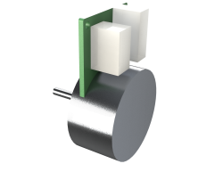 The motors are made by Maxon, they are 50W motors and come with their own PCB into which the motor cable and motor encoder cable can be plugged in. They are connected to the motor mount with three screws. The datasheet of these motors can be found here.
For the transmission from the motor to the wheel which can be seen at the top of this page, a steel gear was glued onto the shaft using Locktite 638 glue. And a POM gear is screwed at the back of the wheel. Two different materials are used for the gears because if they both had the same material, the gears would wear off quickly since they would have the same hardness. Also, POM is self lubricating which is ideal in our situation because we cannot lubricate the gears ourselves since it is an open gearbox.
An important part of designing gears is determining the gear ratio. The most ideal would be to apply inertia matching, such that the inertia “seen” by the motor (so the weight of the robot + gears) is equal to the inertia of the motor itself. Most teams use some gear ratio around 3, ours was always 2.5. Increasing it would mean an increase in torque available to the wheel (so higher acceleration), but a decrease of top speed. Since this was a quite complex calculation for the robots and 2.5 seemed pretty decent already, we decided to look at the available space to adjust the gears. The gear on the wheel is already at its maximum size, as it will otherwise be scraping over the carpet. The only option to increase the gear ratio, was to decrease the number of teeth on the pinion. We had to take into account that undercutting might take place, which might take place when the number of teeth goes below 17 (there are design rules for this). Together with the hunting tooth limitation, we decided to keep the large gear at 45 and set the pinion to 17. The gears were ordered at Hankamp Gears, an Enschede based company that specializes in custom made gears.