First Iteration
In the last section, a concept was made by choosing different solutions to subsystems. Although the choices for these solutions have been made, the front assembly can still be designed in different ways. Therefore, we came up with an initial design which was first created in solidworks and then a prototype of this design was made to see if it worked as expected.
Main Frame Assembly
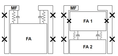
Two different configurations were thought of for the design of the main frame and its connection with the front assembly, these designs are shown in the following figure (where FA means Front Assembly and MF means Main Frame).
The first configuration shows the main frame from which the front assembly is connected with a spring-damper mechanism. However taking the requirement of modularity into account, this suspension cannot be connected to both the front assembly and main frame, as this would obstruct a simple removal of the front assembly from the robot. The second configuration consists of the same main frame but a front assembly made of two parts. The first one will be fixed to the main frame. The damping mechanism will be the connection between the two parts. This configuration allows us to take the front assembly and the damping mechanism out without having to disconnect the shock absorbing elements. This can also be useful for testing purposes since it will not require a complete robot to test it.
There are a couple of other things that have to be considered. Firstly, the chipper could be stationary or it could move along with the front assembly. The advantage of a stationary chipper is that the ball cannot be 'eaten' by the dribbler and it would be easier to make sure that the surface of the ball will be visible for 80% at all times. A moving chipper plate might allow the ball to have a three point contact between dribbler, chipper plate and field at all times which will help catch and keep control of the ball in a better way as explained in ZJUNlict's paper. Secondly, the exact location for the damping should be considered. Indeed, the exact height should be determined. Also, it might be possible and perhaps useful to have damping at the bottom or the top as well. Furthermore, the main frame will act as guiding for the front assembly. If this guiding on the bottom plate is not sufficient, it could be considered to add some extra guiding at the top. This could, for example, be done at the bottom of the middle plate. The main frame could be fixed to the bottom plate with screws or in another way. Fixing it with screws seems to be the simplest solution since it does not have to be replaced or taken out often.
Locking Mechanism
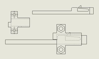
As explained above, the front assembly needs to be attached to the main frame in a way that does not prevent modularity. Therefore, it needs to be easy to disconnect it from the main frame while making sure it is well attached and cannot get loose when the locking mechanism is locked. This mechanism can be seen in the following figure.
It is made of two parts, the first one is a box which will remain fixed on the bottom plate and the other is a pin that slides in the box, gets locked in it with a snap fit while the end of the pin will slide in the main frame and the front assembly to keep it in place. Also, there will be a spring attached to the main frame and the pin, this spring will be compressed when the pin is slided into the box. In order to release the lock, the end of the snap fit needs to be pressed and the pin will slide out of the box due to the spring expanding to push it out. There will be such a locking mechanism on each side of the front assembly.
Damping Mechanism
In order to absorb the impact energy of a ball that hits the front assembly, it was chosen to suspend the front part of the front assembly from the back part, similar to the configuration on the right in the first figure on this page. To realize this, several options are available. The first option is similar to the current solution: put a shock absorbing material in between the two parts of the front assembly which will work as a spring and damper. The other options were either buying a shock-absorber or manufacturing one ourselves, from which the latter was chosen.
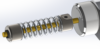
The benefit of designing a shock absorber ourselves is that we can determine the specifications to our needs. However, a conventional shock absorber, where the damper consists out of a piston moving through a viscous fluid, is hard to design and manufacture ourselves in practice. Indeed, it is quite a challenge to make the device resistant to leaking. Therefore, a different type of damper was chosen: a J-damper, often referred to as an inerter. This type of shock absorber transforms the translation of the motion it acts upon into a rotation of a mass, which dissipates the energy. A picture of the final design is shown below.
First Iteration Final Design
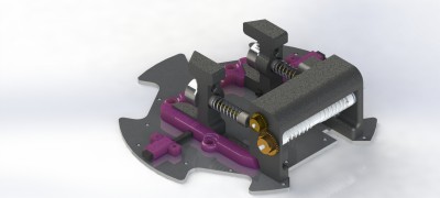
After designing the different parts needed for the new front assembly, the first iteration was finished and a prototype of it was manufactured to see if everything was working as expected. The final design of this iteration can be seen in the following figure.
The enclosure for the dribbler motor as well as the locking mechanism turned out to work really well. The locking mechanism did not need the spring to work properly so it was removed to make the design of it easier. However, there were some minor issues which need to be fixed. First, the inertias of the J-dampers are too big which does not make modularity possible. Indeed, the inertias collide with the front motors when the front assembly is slided on the bottom plate, and once it is in place they touch the back motors. Additionally, the inerters' inertias touch the kicker when the front assembly is slided in the robot. Moreover, there is some friction between the front part of the front assembly and both the bottom plate and the main frame. Furthermore, the top of each back part of the front assembly collides with the cable connectors of the front wheels. Finally, this front part can also move upward when receiving the ball and the guiding system which was thought of would have added more friction, but this is not wanted.
Therefore, a second iteration of this design will be made. It will focus on adding a good guiding system which prevents the front part of the front assembly to move upward. Also, it will prevent friction between the front part of the front assembly and the bottom plate and main frame. Moreover, the back parts will be redesigned in order to prevent them from touching the wheel motors' cables. Finally, the damping mechanism will be redesigned to make sure that the front assembly can be modular.


