Final Iteration
The final iteration of the front assembly has been designed by taking into account the issues found in the first and second iterations, as well as by keeping in mind the things that did work as expected in the first two designs.
The main requirements for this design are the ones already mentioned after doing the damping tests as well as the requirement described in the second iteration which is:
- Design the front assembly such that it is also capable of handling the vertical component of the ball impact forces, since the trajectory of the ball will not be perfectly horizontal.
New Design
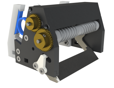
The two figures below show a 3D render of the new design of the front assembly along with a cross-section view of this new design.
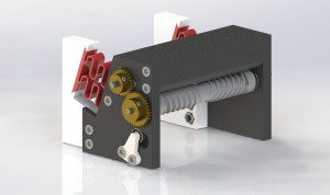
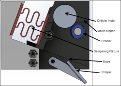
There are few similarities between this design and the first two iterations, like the support for the dribbler motor, the idea of having two parts for the front assembly, one fixed and one moving, with the damping mechanism between these two parts, and the fact that the damping mechanism will be slided in the front assembly.
However, there are many differences with the previous iterations. First, the main frame was removed since it is easier to directly connect the front assembly to the bottom plate with screws. Due to this removal of the main frame, the front assembly takes a lot less space on the bottom plate, which leaves a lot of space for the design of the new solenoids. The main frame was there to guide the moving part of the front assembly to make sure it did not move to the sides. This guiding part was instead put on the fixed part of the front assembly. Also, we added a small 3D printed part (in white in the figure above), which holds a ball bearing in order to prevent the front assembly for moving up and to allow more smooth movement of the front assembly's moving part. Then, an important change is that, upon impact of the ball, the front part can shift back over a slope instead of only moving horizontally. Therefore, the latest requirement mentioned above is taken into account as well.
Furthermore, the damping mechanism was changed. It is now a viscoelastic flexure element, shown in red in the figures above. This flexure is easily interchangeable due to the dove-tail connection, which allows for testing many configurations of such an element, by changing its geometry and material to tweak the performance of receiving the ball. This is a major benefit over the sponges that were glued to the parts. Also, the flexures, as opposed to the sponges, are more predictable in behavior. This predictability contributes greatly to the consistency of the front assembly's performance. Therefore, receiving the ball is more reliable with this new design.
Moreover, the bolted connections in the frame are improved by using inlays of self-locking nuts instead of directly screwing in the plastic. This eliminates the problem of wear-out of the plastic around the screws, hence it improves the rigidity of the front assembly. Finally, most of the parts are designed such that they can be produced with a 3D-printer. This way we can make most parts in-house, instead of relying on outsourced products, reducing production times for the assembly. This allows us to easily incorporate new features on the parts, which in the end gives us more control over the design of the front assembly.
Testing
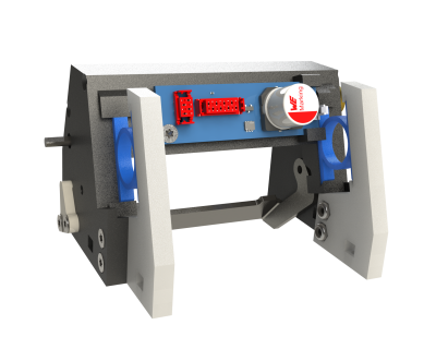
All the parts of the front assembly were 3D printed and put together to see if everything also fitted in real life and not just on solidworks. The white parts at the back in the figure above are in the way of the front wheel motors' cables, and the front part is in the way of the ball sensor so it cannot see the ball, but other than that everything fitted well in the robot. A minor issue which we already knew about was that this front assembly is taller than the previous one. Therefore, it almost touches the middle plate, but since the moving part moves up upon impact with the ball, it would eventually touch the middle plate every time the robot tries to catch the ball, which would prevent the damping mechanism from working optimally. So the middle plate needs to be moved up in order for the front assembly to fit and work properly.
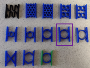
Moreover, the right size, shape and material for the damping flexure had not been determined yet. We decided to try different shapes, sizes and materials, then did the same damping test that was done in October 2021 with these new damping flexures. Different materials were tested, first we used PETG because it was the most flexible material we could print with the Prusa MK3S+. Then, while we were waiting to get a better 3D printer, we tried putting foam earplugs as damping. Finally, we got the Ultimaker S5 which could print with TPU 95A and tough PLA together or TPU 95A on its own. We tried many different shapes using TPU as shown in the following figure, the most flexible ones were the ones with a circle shaped damper, therefore we only tested these. We also tried putting tough PLA on the sides of the dampers, to make the connections between the front assembly and the dampers more sturdy (the blue and green damper in the figure). The black damper in the figure is the one made out of PETG.
The test results can be found here (the tests of these new dampers are written in a different color than black). After doing the tests, we concluded that the TPU 95A damper with a circle of thickness 1.5mm was best (the one circled in purple in the figure above).
Finally, we wanted to test if the dribbler motor heated up or not when the dribbler was on for a long time. The motor is enclosed in the new design which is why we were worried it would heat up. However, even after being on for a couple of minutes, the motor remained cold. Therefore, no redesign of the motor's enclosure is needed.
Improvements
The front assembly was made of eleven parts (excluding the dribbler assembly, the dampers and all the screws and nuts). They were each connected with screws and nuts which made it difficult and time consuming to all connect together, so we merged certain parts together so now the front assembly has seven parts.
Also, as mentioned above, the parts at the back (the white parts in the first figure on this page) are in the way of the front wheel motors' cables so they were redesigned to prevent this issue. The front of the assembly was also redesigned in order for the ball sensor to be able to actually see the ball.
Furthermore, the bearings on the side which are used for a smoother movement of the moving part and also prevent the assembly from moving upwards are expensive, almost 4 euros. So we needed at least 16*2*4euros = 128euros, but of course we would also need spare parts… however, in order to save 150 to 200 euros, we decided to remove those and only have the plastic part to prevent the assembly from moving up.
Moreover, electronics finished their PCB design for the front assembly, so we designed a part attached to the back of the assembly's moving part to keep this PCB in place. As shown in the figure below, one side of the PCB is fixed with a screw and the other is clamped between 3D printed parts.
Finally, the chipper plate was designed to be fixed on the front assembly and move with it. Some modifications might still be done to it to make sure it works properly with the new solenoids. If any modifications are made they will be talked about in the new solenoids section.
Final Design
Here is the final design of the new front assembly with the changes made as explained above. There are many parts in this assembly and we found ourselves stuck sometimes because we did not assemble it in the right order… so we have made a guide on how to assemble it yourselves: Assemble Front Assembly.
As mentioned in the testing section of this page, this front assembly is taller than the one of 20-21. Therefore, the middle plate needs to be moved up by redesigning the motor mounts. The changes made to these parts can be found here.
