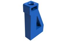
Top Assembly
Top Plate
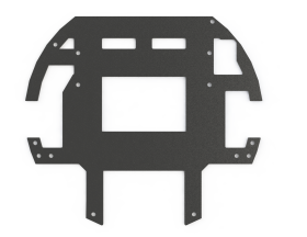
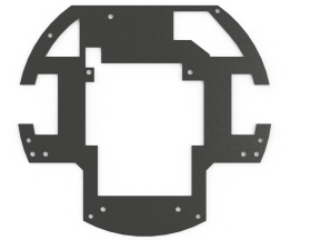
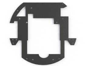
The redesign of the top plate was mainly dependent on the new pcb designs. The first redesign still has the holes that connect to the 20-21 PCBs. The goal of this first redesign was to make the plate firmer and better resistant to impacts.
For the second redesign, the positions of the holes are based on the prototypes of the new set of PCBs. However, even though the holes seemed to be positioned correctly, some components on the PCBs were interfering with the top plate. Furthermore, connecting the motor drivers and the encoder cables to the topboard appeared to be quite difficult. Also the cable of the lipo was difficult to connect to the powerboard. All these issues have been taken into account for the final redesign.
In the final version of the top plate, all holes for the pcb's and connections to the middle plate are in the right location. Cut outs have been made for big components on the PCBs that were interfering with the top plate (especially the circular cutout at the bottom of the plate to prevent collision with two of the kickerboard's capacitors). The redesign also took into account the ability to easily connect cables to the power board and the top board. The thickness of some parts of the plate, that appeared to be quite fragile, has been increased.
Cap Connectors
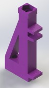
The other component which was redesigned in the top assembly was the cap connectors, which were previously known as PCB holders. These parts were redesigned twice this year, first to prevent the 20-21 top and bottom board from vibrating, disconnecting from the backboard, and breaking. And a second time to fit in with the new PCB designs and have a sturdier connection with the robot's cap.
With the first redesign, the top board could now be slided in between two plastic part, instead of resting on one like in the previous design. This prevented the top board from vibrating, but also the bottomboard since it was stuck between a fixed top plate and a fixed topboard. So this new design was good to prevent damage to the PCBs, however its connection with the cap was still not great. This new design has a slot in which a nut can be put to have a sturdier connection (previously there was a 3D printed thread on the top hole, but these screws are put in and taken out quite often so the thread was wearing off very quickly). The issue with this design is that the nut can fall out quite easily by pulling a bit on the screw that goes through it. Therefore, we redesign this part a second time to fix this issue.
In this final design of the cap connector, the nut can be slided in from the side (instead of from the top), therefore the nut cannot fall off by pulling on the screw that goes through it. Also, the PCBs do not need to be supported anymore since they are sturdily fixed with spacers, so the parts in the previous designs which held the PCBs were removed.
