Dribbler Board
Datasheet, Design on Altium Drive
| Designer | Tijmen Smit |
| Last Version | v1.0 |
| Last Updated | 13 jun 2022 |
The main functionality of this printed circuit board, is driving the dribbler from a PWM signal and providing a place to connect the dribbler encoder.
Design
J2 is used to connect the board to the Power Board. The encoder (see datasheet) is connected to J3 (note that the default connector is changed) which signals are directly forwarded to J2. The used connectors are chosen because of it's robustness against vibrations and the the possibility of polarization, disallowing them to be connected backwards. J1 chosen because used in previous designs, thus the dribblers already have these connectors.
The general design is dc motor pwm driver1) in which N-Chanel MOSFET Q1 is driven by a pwm signal. C1 is a decoupling capacitor. The motor requires big currents, so a big capacitor is used to keep the voltage stable. A smaller capacitor would not store enough energy to supply the switching behavior of the dribbler, hence voltage dipping. This reduces noise on the power lines and keeps the switching transients close to the actual circuitry. Also keep in mind: dV/dt = 1/C * dI/dt. The actual value is probably just a guesstimation of what is needed.
D1 acts as an flyback or snubber diode. This diode was selected because it is capable of handling high voltages. The package contains two diodes of which one is used. R1 is used as a pull down resistor to stop prevent leakage currents from turning on the MOSFET.
Components
Testing
-- Testing code
Changing the encoder connector
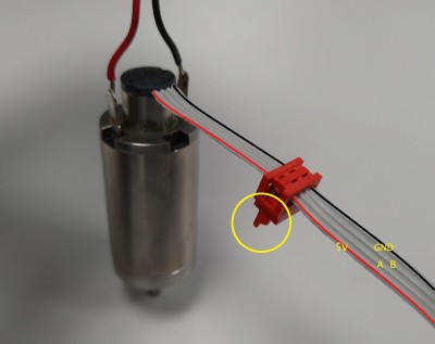
Instead of the default IDC socket connector on the encoder, the decision has been made to change these to a Würth Mini Module (WR-MM) connector. This connector is smaller and can be locked. The figure below shows how this new connector should be connected. Note the little tab on the side of the connector and how this should be oriented with respect or the encoder. Leave approximately xx cm  of cable, the rest can be cut off. Note that the colours on the ribbon cable were added digitally and that the red and black motor cables (going out the top) could be the other way around.
