Omnidirectional Control
Based on a paper written by Raul Rojas at the Freie Universitat Berlin [1]
Variables
| Name / Symbol | Description | Unit |
|---|---|---|
| $\phi$ | The angle of the wheels in the front of the robot ($30^{\circ}$, $\frac{1}{6}\pi$) | $[rad]$ |
| $\theta$ | The angle of the wheels in the back of the robot ($60^{\circ}$, $\frac{1}{3}\pi$) | $[rad]$ |
| $\omega$ | The local angle of the robot (yaw) | $[rad]$ |
| $\gamma$ | The global angle of the robot | $[rad]$ |
| $m_n$ | The motor of wheel $n$ where $n \in \{1,2,3,4\}$ | [-] |
| $f_n$ | The force that is delivered onto wheel $n$ where $n \in \{1,2,3,4\}$ | $[PWM]$ |
| $v_n$ | The velocity that is achieved by a wheel $n$ where $n \in \{1,2,3,4\}$ | $[m/s]$ |
| $v_{\omega, n}$ | The angular velocity that is achieved by a wheel $n$ where $n \in \left\{1,2,3,4\right\}$ | $[rad/s]$ |
| $v_x$ | The velocity of the robot in the $x$ direction in the global frame | $\left[m/s\right]$ |
| $v_y$ | The velocity of the robot in the $y$ direction in the global frame | $\left[m/s\right]$ |
| $v_u$ | The velocity of the robot in the $x$ direction in the local frame | $\left[m/s\right]$ |
| $v_v$ | The velocity of the robot in the $y$ direction in the local frame | $\left[m/s\right]$ |
| $v_{\omega}$ | The angular velocity of the robot | $\left[rad/s\right]$ |
| $R_r$ | The radius of the robot | $[m]$ |
| $R_w$ | The radius of a wheel | $[m]$ |
Conventions
| Matrix name | Matrix |
|---|---|
| $\textbf{f}$ | $(f_1, f_2, f_3, f_4)^T$ |
| $\textbf{m}$ | $(v_1, v_2, v_3, v_4)^T$ |
| $\textbf{v}$ | $(v_x, v_y, R_r v_{\omega})^T$ |
Below you can find a picture of the top view of the robot where the upper section is the front of the robot
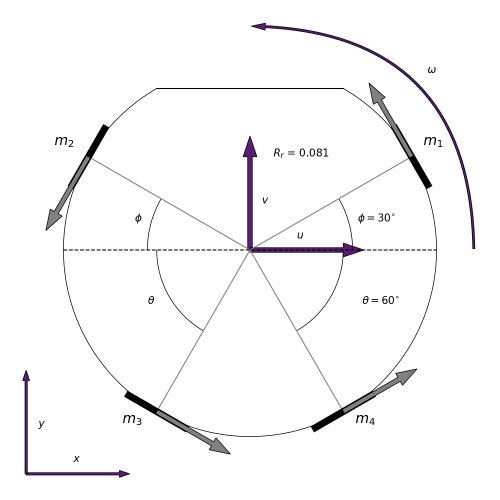
This picture was generated with matplotlib, you can find the original source code over here.
Matrices
In order to translate the global velocities into local velocities, we use the following rotation matrix [2] $$ r = \begin{pmatrix} \cos\omega & -\sin\omega & 0 \\ \sin\omega & \cos\omega & 0 \\ 0 & 0 & 1 \end{pmatrix} $$
We use the following velocity coupling matrix $$ D = \begin{pmatrix} -\sin\phi & \cos\phi & R_r \\ -\sin\phi & -\cos\phi & R_r \\ \sin\theta & -\cos\theta & R_r \\ \sin\theta & \cos\theta & R_r \end{pmatrix} $$
The pseudoinverse of the velocity coupling matrix is the following
$$ D^\dagger = \frac{1}{2} \begin{pmatrix} -\frac{1}{\sin\theta+\sin\phi} & -\frac{1}{\sin\theta+\sin\phi} & \frac{1}{\sin\theta+\sin\phi} & \frac{1}{\sin\theta+\sin\phi} \\ \frac{\cos\phi}{\cos^2\theta+\cos^2\phi} & -\frac{\cos\phi}{\cos^2\theta+\cos^2\phi} & -\frac{\cos\theta}{\cos^2\theta+\cos^2\phi} & \frac{\cos\theta}{\cos^2\theta+\cos^2\phi} \\ \frac{\sin\theta}{\sin\theta+\sin\phi} & \frac{\sin\theta}{\sin\theta+\sin\phi} & \frac{\sin\phi}{\sin\theta+\sin\phi} & \frac{\sin\phi}{\sin\theta+\sin\phi} \end{pmatrix} $$
Note: This matrix slightly differs from the matrix provided in the paper. This pseudo-inverse has been calculated with the help of Wolfram Alpha and does behave as expected. It seems that the matrix from the paper is incorrect.
The PWM factor is calculated as follows $$ \text{speed constant} = \frac{2\pi}{60} \times \text{motor speed constant} $$ $$ \text{PWM factor} = \frac{1}{\text{speed constant}} \times \frac{\text{PWM}_{max}}{v_{max}} \times \text{gear ratio} $$
The encoder factor is calculated as follows $$ \text{encoder factor} = \frac{2\pi}{\Delta t \times \text{gear ratio} \times \text{pulses per rotation}} $$
Implementation
Instructions to wheels
The actual implementation in C can be found at our GitHub
Translate the global velocity and angle to x and y velocity components. $$ \left(v_x, v_y \right)^T = \left(\sin\gamma, \cos\gamma \right)^T \times v $$
Translate the global x and y velocity components into local velocity components. $$ \left(v_u, v_v, v_{\omega} \right)^T = r \times \left(v_x, v_y, v_{\omega} \right)^T $$
Determine the speeds for each wheel. $$ \left(v_1, v_2, v_3, v_4 \right)^T = D \times \left(v_u, v_v, v_{\omega} \right)^T $$
Translate the velocities into angular velocities. $$ \left(v_{\omega,1}, v_{\omega,2}, v_{\omega,3}, v_{\omega,4} \right)^T = \frac{1}{R_w} \times \left(v_1, v_2, v_3, v_4 \right)^T $$
Translate the velocities into forces. $$ \left(f_1, f_2, f_3, f_4 \right)^T = \text{PWM factor} \times \left(v_{\omega,1}, v_{\omega,2}, v_{\omega,3}, v_{\omega,4} \right)^T $$
Wheels to feedback
The actual implementation in C can be found at our GitHub
Translates encoder pulses to angular wheel velocities. $$ \left(v_{\omega,1}, v_{\omega,2}, v_{\omega,3}, v_{\omega,4} \right)^T = \text{Encoder factor} \times \left(p_1, p_2, p_3, p_4 \right)^T $$
Translates the angular wheel velocities into wheel velocities. $$ \left(v_1, v_2, v_3, v_4 \right)^T = R_w \times \left(v_{\omega,1}, v_{\omega,2}, v_{\omega,3}, v_{\omega,4} \right)^T $$
Translates wheel velocities to local $v_u$, $v_v$ and $v_{\omega}$ velocities. $$ \left(v_u, v_v, R_r v_{\omega} \right)^T = D^\dagger \times \left(v_1, v_2, v_3, v_4 \right)^T $$
Translates local velocities to global velocities. $$ \left(v_x, v_y, R_r v_{\omega} \right)^T = r^{-1} \times \left(v_u, v_v, R_r v_{\omega} \right)^T $$
Translates global velocities into an angle and velocity $$ v = \sqrt{v_x^2 + v_y^2} $$ $$ \gamma = \tan^{-1} \frac{v_y}{v_x} $$