Control
Welcome to the Control section of the RoboTeam Twente Wiki!
The control sub-team forms the bridge between the software and hardware in the robot. They are mainly responsible for the movement of the robot and processing data coming from sensors on the robot. Once the AI has determined a sequence of actions that a robot should take, the control team will need to make sure that the robot actually executes these. The main part of this is the control applied during the path planning phase, where to robot has to move from A to B over a given path.
Control in engineering focuses on the performance of a mechatronic system by eliminating the systems error. This error in basic terms is the difference between the set-point (SP) and a measured process variable (PV). The input could for example be the desired speed of the robot and the output is the actual speed of the robot. The wheel speeds of the robot are measured by encoders, which can then be translated to velocities in $x$- and $y$-direction which are used for feedback. The error of the system is the difference between the measured speeds and the speeds that are commanded to the robot (error = SP-PV = (commanded speed) - (measured speed)).
In this wiki you will find information that is mainly separated into three big sections: State Estimation, State Control and General Information. Where the first section explains al about allowing the robot to determine its current state (velocity/angle/etc.), the second sections elaborates on allowing us to actually trigger the actuators in the robot to make it move. In case of information that is relevant for both sections, or it is simply generic, then it can be found in the General Information section.
State Estimation
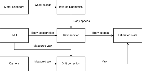
State estimation is the art of understanding what the robot is doing at this very moment. In order to achieve this, the robot receives information from the AI and information from its sensors, such as the IMU, located on the topboard, or the encoders from the motors (wheels and dribbler). When one combines all these pieces of information they are able to quite accurately estimate the current state of the robot.
In the image above, you can find a (simplified) data flow of all the sensors and operations performed on the data that help us estimate the state of the robot. In the following articles you can read about each process and about how it has been implemented in our code.
Technical Details
State Control
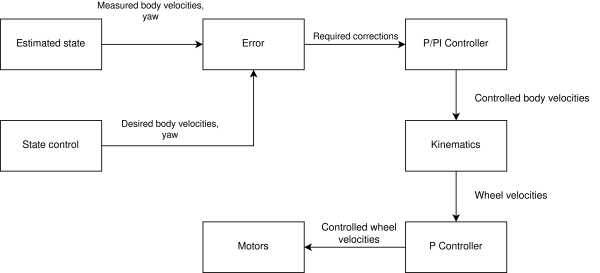
Once the robot is aware of its current state it will try to correct itself in such a way that it achieves the desired state. This happens during the state control phase. The first step is to figure out the difference between our current state and the desired state, the error. Our state is defined by our velocity in the forward (x), sideways (y), and rotational (ω) direction. Once we're aware of the error, we start compensating for it. This happens in two distinct phases. First, we control our body velocities with a PI controller. Then, we control each wheel with an additional P controller. Eventually, this is translated in the power that each individual motor should deliver. Below you can find a simplified version of our control system.
In the technical section you will be able to find articles explaining each distinct phase that contributes towards the control on our robot.
Code generation
The control code is no longer written by hand, instead we use MATLAB Simulink to generate it for us.
Required software
MATLAB Simulink with the following add-ons:
- Embedded Coder
- Simulink Coder
- Simulink Compiler
- MATLAB Coder
- MATLAB Compiler
Running the code generation for our repository additionally requires a MATLAB version of 2024b or newer, as well as the DSP System Toolbox add-on.
Initial set-up
To set up code generation for a new part of the system (or a new system entirely), go through the following steps:
- Make a new Simulink model containing at least the desired input/output ports
- Open the Embedded Coder app, let it change the target to ert.tlc if prompted.
- Go to Settings→Solver→Solver selection and select the Fixed-step solver with a timestep that corresponds to your desired update frequency. It could be a good idea to put a variable called Ts in your model workspace to put in this field.
- Change any additional settings to taste.
- Try to generate code using the Embedded Coder app
Interfacing with an existing C-codebase
The C-code generated by Simulink needs to be called to do anything. Configuring the code generation for easy interfacing with an existing codebase can be done using the following procedure:
- In Simulink with the model open, open the Embedded Coder App to enable the C-Code tab.
- Go to C-Code→Code Interface→Individual Element Code Mappings to open the Code Mappings interface.
- In the Code Mappings interface, go to the Functions tab.
- There should be two functions here, one for initialization and one called step. Double-click the function preview of the step function.
- Then configure the arguments of this function to be the in-and-out ports of the model. You may have to hit the Get default button to be able to do this.
- Re-generate the code.
- Make sure the generated code is in a place where your toolchain can find it.
- Call the initialization function in from your C-code, and also make sure to call the step function with the same time-interval as is configured in the Simulink model.

